
As should be obvious from this blog, I am somewhat drawn to clever and minimalistic implementations of consumer electronics. Sometimes quite a bit of ingeniosity is going into making something “cheap”. The festive season is a boon to that, as we are bestowed with the latest innovation in animated RGB Christmas lights. I was obviously intrigued, when I learned from a comment on GitHub about a new type of RGB light chain that was controlled using only the power lines. I managed to score a similar product to analyze it.
The product I found is shown below. It is a remote controlled RGB curtain. There are many similar products out there. What is special about this one, is that there are groups of LEDs with individual color control, allowing not only to set the color globally but also supporting animated color effects. The control groups are randomly distributed across the curtain.

The same type of LEDs also seems to be used in different products, like “rope-light” for outside usage. A common indication for this LED type seems to be the type of remote control being used, that has both color and animation options (see above).
There seems to be an earlier version of similar LEDs (thanks to Harald for the link) that allows changing global color setting in a similar scheme but without the addressability.
Physical analysis
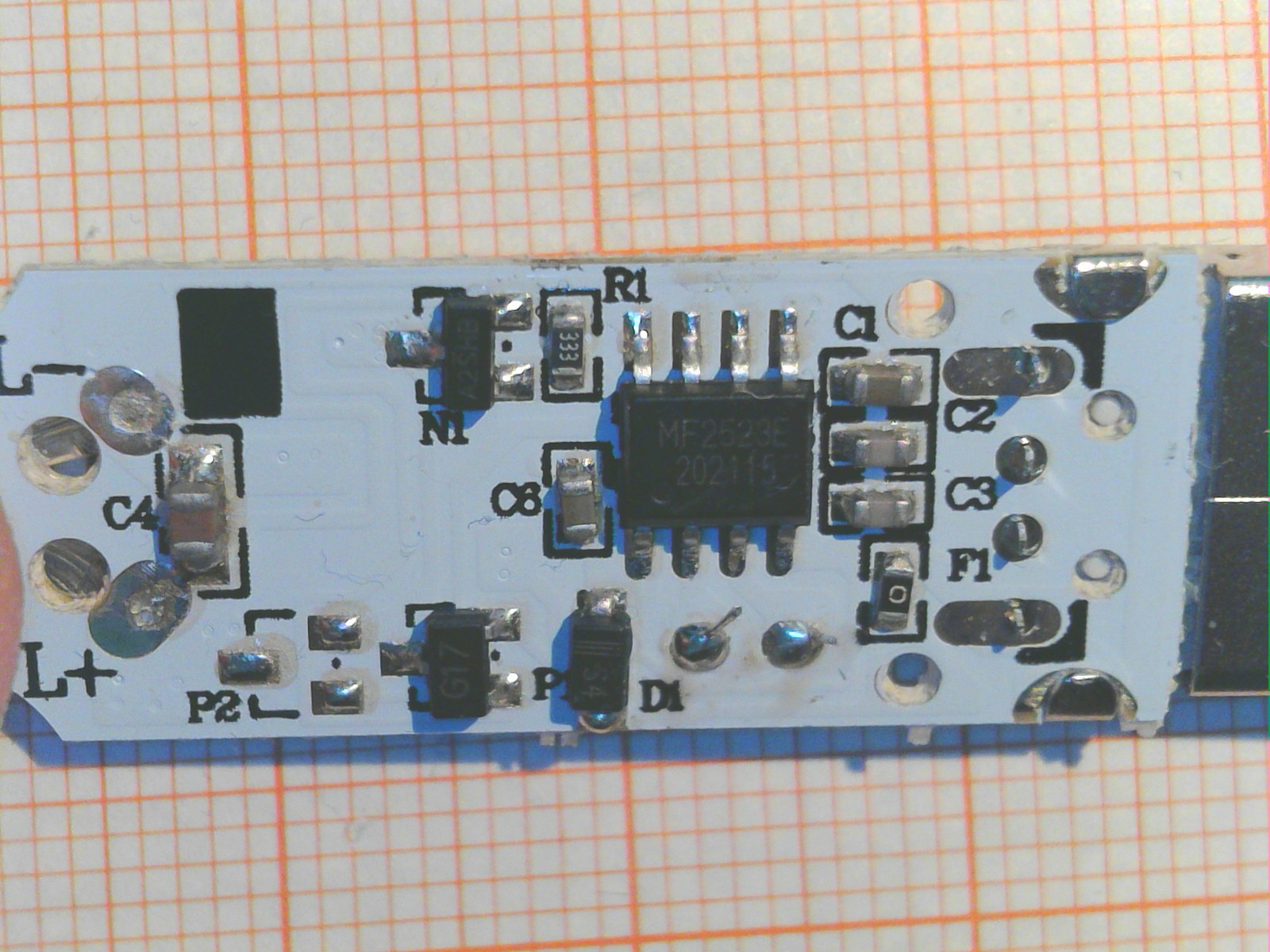
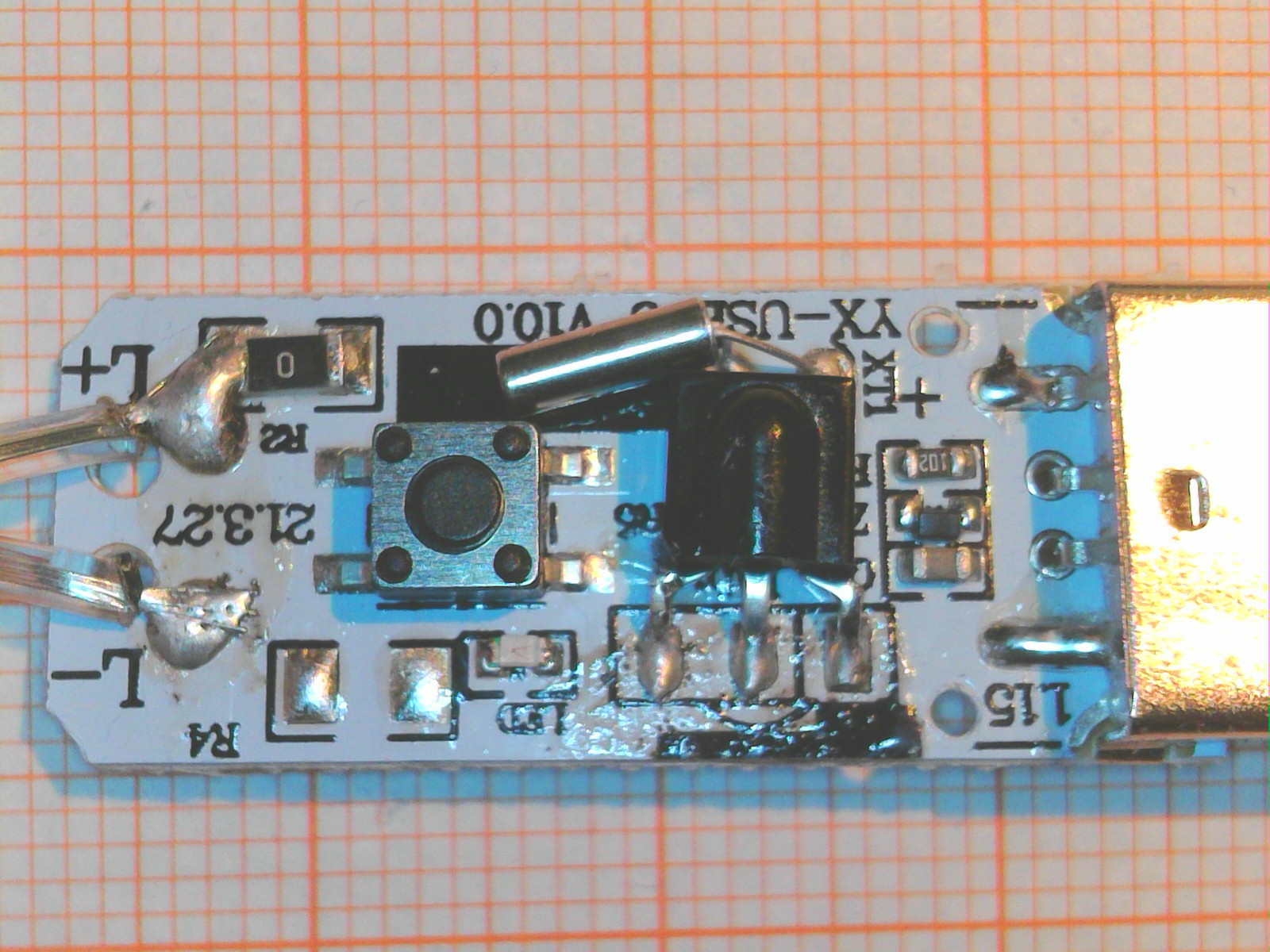
Let’s first take a quick look at the controller. The entire device is USB powered. There is a single 8 pin microcontroller with a 32.768kHz quarz. Possibly to enable reliable timing (there is a timer option on the remote controler) and low power operation when the curtain is turned off. The pinout of the MCU seems to follow the PIC12F50x scheme which is also used by many similar devices (e.g. Padauk, Holtek, MDT). The marking “MF2523E” is unfamiliar though and it was not possible to identify the controller. Luckily this is not necessary to analyze the operation. There are two power mosfets which are obviously used to control the LED string. Only two lines connect to the entire string, named L- (GND) and L+.
All 100 (up to 300 in larger versions) LEDs are connected to the same two lines. These types of strings are known as “copper string lights” and you can see how they are made here (Thanks to Harald from µC.net for the link!). It’s obvious that it is easier to change the LED than the string manufacturing process, so any improvement that does not require additional wires (or even a daisy chain connection like WS2812) is much easier to introduce.


Close up images of a single LED are shown above. We can clearly see that there is a small integrated circuit in every lightsource, and three very tiny LED chips.

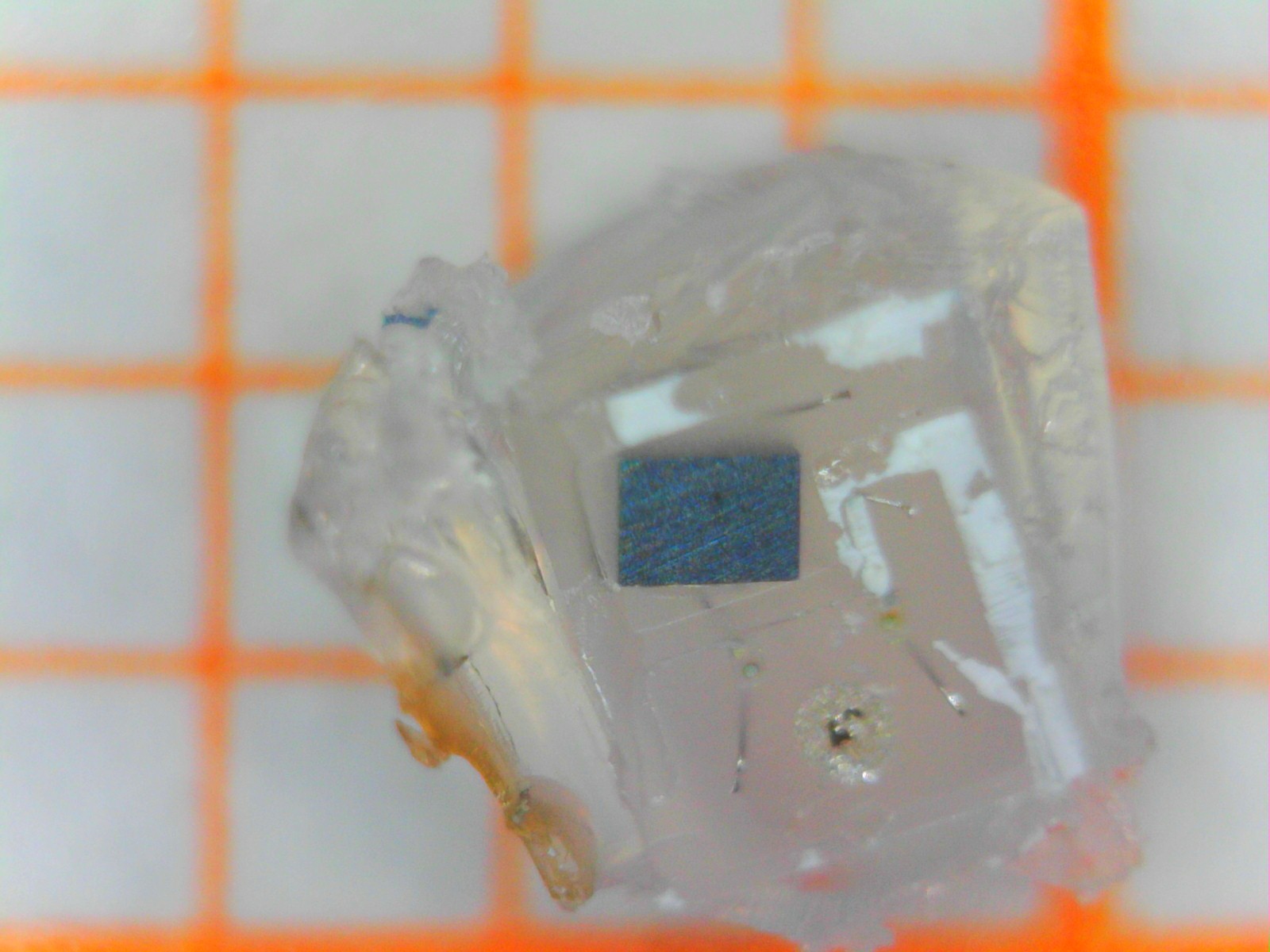
Trying to break the LED apart to get a better look at the IC surface was not successful, as the package always delaminated between carrer (The tiny pcb on the left) and chips (still embedded in the epoxy diffusor on the right). What can be deduced however, is that the IC is approximatly 0.4 x 0.6 = 0.24 mm² in area. That is actually around the size of a more complex WS2812 controller IC.
LED Characterization
Hooking up the LEDs directly to a power supply caused them to turn on white. Curiously there does not seem to be any kind of constant current source in the LEDs. The current changes direclty in proportion to the applied voltage, as shown below. The internal resistance is around 35 Ohms.

This does obviously simplify the IC a lot, since it basically only has to provide a switch instead of a current source like in the WS2812. It also appears that this allows to regulate the overall current consumption of the LED chain from the string controller by changing the string voltage and control settings. The overall current consumption of the curtain is between 300-450 mA, right up to the allowable maximum of power draw of USB2.0. Maybe this seemingly “low quality” solution is a bit more clever than it looks at the first glance. There is a danger of droop of course, if too much voltage is lost over the length of the string.
How Is It Controlled?
Luckily, with only two wires involved, analyzing the protocol is not that complex. I simply hooked up one channel of my oscilloscope to the end of the LED string and recorded what happened when I changed the color settings using the remote control.

The scope image above shows the entire control signal sequence when setting all LEDs to “red”. Some initial observations:
- The string is controlled by pulling the entire string voltage to ground for short durations of time (“pulses”). This is very simple to implement, but requires the LED controller to retain information without external power for a short time.
- We can directly read from the string voltage whether LEDs are turned on or off.
- The first half of the sequence obviously turns all LEDs off (indeed, the string flickers when changing color settings), while the second half of the sequence turns all LEDs on with the desired color setting.

Some more experimentation revealed that the communication is based on messages consisting of an address field and a data field. The data transmission is initiated with a single pulse. The count of following pulses indicates the value that is being transmitted using simple linear encoding (Which seems to be similar to what ChayD observed in his string, so possibly the devices are indeeed the same). No binary encoding is used.
Address and data field are separated by a short pause. A longer pause indicates that the message is complete and changes to the LED settings are latched after a certain time has passed.

My findings are summarized in the diagram above. The signal timing seems to be derived from minimum cycle timing of the 32.768kHz Crystal connected to the microcontroller, as one clock cycle equals ~31 µs. Possibly the pulse timing can be shortened a bit, but then one also has to consider that the LED string is basically a huge antenna…
| Address Field | Function |
| 0 | Unused / No Function |
| 1 … 6 | Address one of six LED subgroubs (zones), writes datafield value into RGB Latch. |
| 7 | Address all LEDs at once (broadcast), adds datafield value to RGB latch content. |
| RGB Latch Value | RGB encoding |
| 0 (000) | Turn LEDs off (Black) |
| 1 (001) | Red |
| 2 (010) | Green |
| 3 (011) | Yellow (Red+Green) |
| 4 (100) | Blue |
| 5 (101) | Magenta (Red+Blue) |
| 6 (110) | Cyan (Green+Blue) |
| 7 (111) | White |
The address field can take values between 1 and 7. A total of six different zones can be addressed with addresses 1 to 6. The data that can be transmitted to the LED is fairly limited. It is only possible to turn the red, green and blue channels on or off, realizing 7 primary color combinations and “off”. Any kind of intermediate color gradient has to be generated by quickly changing between color settings.
To aid this, there is a special function when the address is set to 7. In this mode, all zones are addressed at the same time. But instead of writing the content of the data field to the RGB latch, it is added to it. This allows, for example, changing between neighbouring colors in all zones at once, reducing communication overhead.

This feature is extensively used. The trace above sets the string colour to “yellow”. Instead of just encoding it as RGB value “011”, the string is rapibly changed between green and red, by issuing command “7,1” and “7,7” alternatingly. The reason for this is possibly to reduce brightness and total current consumption. Similar approaches can be used for fading between colors and dimming.
Obviously the options for this are limited by protocol speed. A single command can take up to 1.6ms, meaning that complex control schemes including PWM will quickly reduce the maximum attainable refresh rate, leading to visible flicker and “rainbowing”.
It appears that all the light effects in the controller are specifically built around these limitation, e.g. by only fading a single zone at a time and using the broadcast command if all zones need to be changed.
Software Implementation
Implementing the control scheme in software is fairly simple. Below you can find code to send out a message on an AVR. The code can be easily ported to anything else. A more efficient implementation would most likely use the UART or SPI to send out codes.
The string is directly connected to a GPIO. Keep in mind that this is at the same time the power supply for the LEDs, so it only works with very short strings. For longer strings an additional power switch, possibly in push-pull configuration (e.g. MOSFET), is required.
#include <avr/io.h>
#include <util/delay.h>

// Send pulse: 31 µs low (off), 31 µs high (on)
// Assumes that LED string is directly connected to PB0
void sendpulse(void) {
	DDRB |= _BV(PB0);
	PORTB &= ~_BV(PB0);
	_delay_us(31);
	PORTB |= _BV(PB0);
	_delay_us(31);
}

// Send complete command frame
void sendcmd(uint8_t address, uint8_t cmd) {

	sendpulse(); // start pulse
	for (uint8_t i=0; i<address; i++) {
		sendpulse(); }

	_delay_us(90);

	sendpulse(); // start pulse
	for (uint8_t i=0; i<cmd; i++) {
		sendpulse(); }
	_delay_us(440);
}
It seems to be perfectly possible to control the string without elaborate reset sequence. Nevertheless, you can find details about the reset sequence and a software implementation below. The purpose of the reset sequence seems to be to really make sure that all LEDs are turned off. This requires sending everything twice and a sequence of longer duration pulses with nonobvious purpose.

// Emulation of reset sequence
void resetstring(void) {
	PORTB &= ~_BV(PB0);  // Long power off sequence
	_delay_ms(3.28);
	PORTB |= _BV(PB0);
	_delay_us(280);

	for (uint8_t i=0; i<36; i++) {  // On-off sequence, purpose unknown
		PORTB &= ~_BV(PB0);
		_delay_us(135);
		PORTB |= _BV(PB0);
		_delay_us(135);
	}

	_delay_us(540);
	// turn everything off twice.
        // Some LEDs indeed seem to react only to second cycle.
        // Not sure whether there is a systematic reason

	for (uint8_t i=7; i>0; i--) {
		sendcmd(i,0);
	}

	for (uint8_t i=7; i>0; i--) {
		sendcmd(i,0);
	}
}
Pulse Timing And Optical Measurements
Update: To understand the receiver mechanism a bit more and deduce limits for pulse timing I spent some effort on additional measurements. I used a photodiode to measure the optical output of the LEDs.

An exemplary measurement is shown above. Here I am measuring the light output of one LED while I first turn off all groups and then turn them on again (right side). The upper trace shows the intensity of optical output. We can see that the LED is being turned off and on. Not surprisingly, it is also off during “low” pulses since no external power is available. Since the pulses are relatively short this is not visible to the eye.

Taking a closer look at the exact timing of the update reveals that around 65µs pass after the last pulse in the data field until the LED setting is updated. This is an internally generated delay in the LED that is used to detect the end of the data and address field.
To my surprise, I noticed that this delay value is actually dependent on the pulse timing. The timeout delay time is exactly twice as long as the previous “high” period, the time between the last two “low” pulses.

This is shown schematically in the parametrised timing diagram above.
An internal timer measures the duration of the “high” period and replicates it after the next low pulse. Since no clock signal is visible in the supply voltage, we can certainly assume that this is implemented with an analog timer. Most likely a capacitor based integrator that is charged and discharged at different rates. I believe two alternating timers are needed to implement the full functionality. One of them measures the “on”-time, while the other one generates the timeout. Note that the timer is only active when power is available. Counting the pulses is most likely done using an edge detector in static CMOS logic with very low standby power that can be fed from a small on-chip capacitor.
The variable timeout is actually a very clever feature since it allows adjusting the timing over a very wide range. I was able to control the LEDs using pulsewidths as low as 7 µs, a significant speed up over the 31 µs used in the original controller. This design also makes the IC insensitive to process variation, as everything can be implemented using ratiometric component sizing. No trimming is required.
See below for an updated driver function with variable pulse time setting.
#define basetime_us 10
#define frameidle_us basetime_us*5  // cover worst case when data is zero

void sendcmd(uint8_t address, uint8_t cmd) {

	for (uint8_t i=0; i<address+1; i++) {
		sendpulse();
	}

	_delay_us((basetime_us*3)/2);

	for (uint8_t i=0; i<cmd+1; i++) {
		sendpulse();
	}
	_delay_us(frameidle_us);
}

// Send pulse
void sendpulse(void) {
		PORTB &= ~_BV(PB0);
		_delay_us(basetime_us);
		PORTB |= _BV(PB0);
		_delay_us(basetime_us);
}
Conclusions
All in all, this is a really clever way to achieve a fairly broad range of control without introducing any additional data signals and while absolutely minimizing the circuit overhead per light source. Of course, this is far from what a WS2812 and clones allow.
Extrapolating from the past means that we should see of more these LEDs at decreasing cost, and who knows what kind of upgrades the next Christmas season will bring.
There seem to be quite a few ways to take this scheme further. For example by finding a more efficient encoding of data or storing further states in the LEDs to enable more finely grained control of fading/dimming. May be an interesting topic to tinker with…


Hey Tim,
Have you played with the non-specified data retention period of the tiny “cheap” micros? We’ve all likely seen some latent data hanging around. Maybe you could use a Padauk or other for a similar evil purpose if you got the power-off timing right.
C. Barry Ward
perverting electronics since 1975
I like your thinking, already had similar thoughts 🙂
If using a microcontroller to implement such a scheme, one could of course use an additional capacitor. On chip this is a bit more difficult. I am still wondering whether there is a timing circuit that is active during the “no power” periods or whether it is possible to get away without. Currently I am leanding towards this being an edge detector only.
I’ve done similar things (albeit longer delays) for HVAC delay-on-break where the timing was controlled by an external RC delay on a pin. (charged fast via a diode and discharging with the power off through the R) port flips to read the cap remaining when the power returns to determine how long the power was off.
With a little bit of temperature compensation and some part characterization you can get pretty good timing without any power whatsoever. And BTW, electrolytics are not as evil as the internet would portray…
B
Also, I’d bet good beer that you could do milliseconds of memory with just the stray charge on a pin or (god forbid) a (clean, dry) PCB trace.
Hm… Let’s assume we have a capactor that powers the circuit during the “off” phase and we can remove charge until the voltage across the capacitor has redcued by 1V. Then:
Q=C*deltaV=I*t -> C = I * t/1V
If t=10µs, and I=1µA, then C=10pF. 1µA should be plenty for CMOS leakage current , so the capacitance can probably be even lower.
If we use a microcontroller with I=500µA, then we already need 5nF. Still doable, just not on chip.
I’m still thinking that the instant you think you can kill all of the charge in the chip “instantly” you will find that it is impossible. Internal bistable nodes that are pulling down in normal operation (a zero) must get to a point during the powering down where the pulldown FET (or other structure) does not have enough charge to stay on but has enough charge to determine the likely turn on state on the next power up. Probably similar for the one states.
While your basic IQ calculation is fine, there are an almost infinite set of conditions that will change when the chip operation goes to DC and the charges stop getting pushed around. With testing you will probably find that some areas, maybe the the ones with recurrent structures (registers, ram etc) behave the way you need to remember something.
My biggest concern with using this method in production might be leakage variation over temperature and process but even that could be characterized to find a timing, data holding structure, and suitable VDD to optimize the SOA for this trick.
I expect that after I had about 10 zillion of these in production the manufacturer would change the process or chip layout and I’d have to find another sweet spot, ram/register or magic operating zone to keep production going.
Welcome to product development, manufacturing, and continuation engineering…….
Oh, and if I was not using this for a fun non-life-support product, some customer would ask me to guarantee that some micro (or other thing) could not possibly retain some secret data…. here we go again….(FETs on all the pins, heaters to raise the leakage, yada… 🙂
>Internal bistable nodes that are pulling down in normal operation (a zero) must get to a point during the powering down where the pulldown FET (or other structure) does not have enough charge to stay on but has enough charge to determine the likely turn on state on the next power up. Probably similar for the one states.
Well, I would assume that one has to conciously design for this type of operation and make sure that parts of the circuit that need to retain state have an isolated power net that is not pulled to ground.
I sketched out here, how this may be done with an MCU:
https://hackaday.io/project/183709-reverse-engineering-powerline-controlled-rgb-light/log/202615-emulating-the-powerline-control-scheme-with-a-mcu
Implementing a simular functionality on-chip would require moving the diode and capacitor on-die and using it only to power the esssential circuits. (e.g. some registers for state retention).
>My biggest concern with using this method in production might be leakage variation over temperature and process but even that could be characterized to find a timing, data holding structure, and suitable VDD to optimize the SOA for this trick.
On the other hand, the device models for on-chip primitives are much better than for discrete components and you can cover all operational conditions and process variation in your simulation.
Of course, utilizing some phantom state retention effects in a microcontroller you have not designed is asking for trouble.
“Of course, utilizing some phantom state retention effects in a microcontroller you have not designed is asking for trouble.”
I’d argue that you may be able to characterize a black box from the outside and determine it’s behavior and safe operating areas. It might not work (well) with any parts at all.. but if/when you found a part type that did, particularly one that was not perturbed by a good range of operating temperature and voltage you could reliably exploit it. (based on a good sample size of course)
You might have to design incoming inspection tests (including destructive ones) to look for design changes but modern IC processes are really fantastic and would likely guarantee that parts from the same lot would behave exactly the same part to part.
If you want to see scary iffy parts with wild process variations wrangled into manufacturable products just look back in history at PNP Germanium circuits. Try building a working circuit with some CK722’s. It’s almost impossible but people did and with amazing results.
Also, if you or other readers don’t have one or access to one, get yourself a TEK 576 and run it for awhile. It will give you a perspective and education a modern SMU just can’t easily match. Being able to twist a few knobs and go from zero to 5V, or zero to 1600V (or any other range) at up to 200W, match the load impedance, and see a VI plot instantly on a screen – for a LED, a string of LEDS with weird wiring, an IC pin and it’s ESD diodes or a pin’s output FET, the old 576 will tell you things not mentioned in the data sheets. And if necessary, you can even test transistors with them….
B
How does a single LED know which zone it is in?
I would assume that this is either programmed into the LED while testing it, or it is hardcoded on the silicon chip.
Re: ‘The trace above sets the string colour to “yellow”. Instead of just encoding it as RGB value “011”, the string is rapibly changed between green and red, by issuing command “7,1” and “7,7” alternatingly.’ – You probably meant to say “7,1” (all red) and “7,2” (all green). Or did I get the protocol wrong? Interesting that the uC in the LEDs can take all those power interruptions.
What I don’t get: Why is not feasible to control an individual LED by the (unique) address of its chip? The ID could even be assigned randomly if the controller’s firmware accommodates for it. With some clever binary encoding/grouping it shouldn’t take too long to transmit the control sequence.
command “7” is a special broadcast mode that does not write the value in the data field, but adds it to the LED RGB register. The reason for that is that it allows changing groups of different colors as well.
Certainly it should be possible to extend the protocol to address LEDs individually. But the question is, how do you assign addresses to LEDs?